The wirebasics CT-16 Continuity Tester
One- 110VAC to 6VDC Adaptor
Two- Ribbon Cables, 24” in length
Two- PCB-16POS-DAPT-ST adaptor boards
Getting Started
Plug the power adaptor into an AC outlet and connect the round plug to the jack at the rear of the CT-16. Turn on the power switch.
Learning the Controls:
You will see on the front panel a column of switches marked “SPLICE SET” these switches are used to program the CT-16 in order to identify test points that will be connected to splices.
If your harness or cable assembly has only straight through connections (no splices) then you will need to assure that all the switches in the “SPLICE SET” column are set to the “OFF” position.
You will also see on the front panel a column of switches marked “LAST WIRE SELECT” these switches are used to program the CT-16 in order to identify the last test point, which will be tested. ONE of these switches must be in the right hand position at any given time but ONLY ONE. Having more than one switch in the right hand position will not damage the unit, however this condition will cause the unit to malfunction.
The light indicators on the panel that are marked “TX” are the transmit diagnostics indicators. The light indicators on the panel that are marked “RX” are the receive diagnostics indicators.
Either the “PASS” or “FAIL” light indicators will illuminate upon the conclusion of each test cycle.
To verify your CT-16, perform the following functionality test.
Using one of the ribbon cables supplied with the unit plug the cable directly between the “TX” and the “RX” connectors on the front panel.
Assure that all of the “SPLICE SET” switches are in the “OFF” position. Assure that the “LAST WIRE SELECT” switch, #16 (only), is positioned to the right.
Turn on the tester and press the “TEST” button.
All of the “TX” and “RX” indicators should be lit and the “PASS” indicator should be lit also. If the “FAIL” indicator is lit, check your cable to be sure it is not damaged. If you experience any problems call the number on page 9.
It is a good idea to perform this procedure on both of the supplied ribbon cables during setup.
It is important to understand that the CT-16 is designed for point to point testing. This means that it is expecting for the signal on pin 1 of TX to return on pin 1 of RX and so on. This rule of operation will be important for you remember when setting up the CT-16.
The only exceptions to this rule are when you have programmed the CT-16 for testing assemblies which contain splices. Setting up the CT-16 for splices is covered in detail in the next section.
Testing Assemblies with Splices
The most important rule to remember when setting up to test splices is that….
TEST POINTS THAT ARE CONNECTED TO SPLICES MUST BE GROUPED TOGETHER
When you toggle the “SPLICE SET” switches to the “ON” position you are programming the tester to expect a splice connection between the two test points associated with that switch. For example, if you select the “ON” position for 2-3, and 3-4, then you have programmed the tester to expect a single wire connected to point 2 of the TX connector to return on wires 2,3,and 4 on the RX connector. In this case pins 3 and 4 on the TX connector must be left unused.
The diagram below will help you understand how to correctly connect your harness or cable to the
CT-16. Also visit www.wirebasics.com for more illustrations.
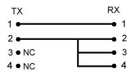
Switch settings for the example above are…
Splice set 1-2 = OFF
Splice set 2-3 = ON
Splice set 3-4 = ON
Splice set (all remaining) = OFF
Last Wire Select = # 4 only
Examples and Switch Settings
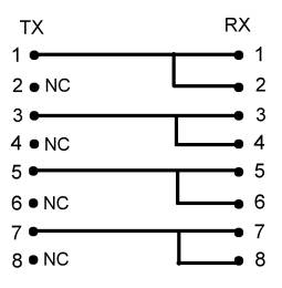
Switch settings for the example above are…
Splice set 1-2 = ON
Splice set 2-3 = OFF
Splice set 3-4 = ON
Splice set 4-5 = OFF
Splice set 5-6 = ON
Splice set 6-7 = OFF
Splice set 7-8 = ON
Splice set (all remaining) = OFF
Last Wire Select = # 8 only
Also visit www.wirebasics.com for more illustrations.
Diagnostics
Diagnosing errors in assemblies being tested with the CT-16 is easy to learn and you will become an expert very quickly.
Connect both of the 16 position adaptor boards to the CT-16 with the cables supplied. Cut seventeen pieces of small gauge wire about 8 inches in length. Strip the ends ¼ inch. One at a time, press down the small tabs on each of the terminal blocks and insert a wire from pin 1 of TX to pin 1 of RX, pin 2 of TX to pin 2 of RX, and so on until you have populated the entire set with one wire left over.
Assure that all “SPLICE SET” switches are off and that the “LAST WIRE SELECT” switch #16 (only) is in the right hand position. Press the test button and you should see all TX and RX indicators lit and the “PASS” indicator lit. If not, the next section will help you fix the problem.
You now have a learning assembly connected to the tester. Introduce an error by removing one end of one wire to create an “OPEN”. Press the “RESET” button and then the “TEST” button. The test will stop prematurely and the “FAIL” indicator will be lit. The corresponding failed circuit diagnostic indicator will be lit it the TX column while the RX should be off. This indicates an “OPEN” in the assembly and the indicator number will correspond with the number on the test point you removed the wire from. Reconnect the wire and the test will complete with a “PASS”.
Introduce an error by using the left over wire. Place it between any two test points to create a “SHORT”. Press the “TEST” button. In the RX column you will see a lit indicator and the “FAIL” indicator will also be lit, but the TX will not be lit. This condition indicates a “SHORT” and the numbered indicators tell you exactly where to find it.
“MISWIRES” are simply combinations of “OPENS” and “SHORTS” and they will be detected and located in the same manner.
Troubleshooting
Anytime you are having unusual behavior with the CT-16 the first course of action is to connect a known good ribbon cable directly between the TX and RX ports on the front panel. Press the TEST button to verify the tester and the cable. If you receive a “PASS” continue to the next section. If you receive a “FAIL” check the switch positions to assure that all of the “SPLICE SET” switches are OFF and the the “LAST WIRE SELECT” #16 (only) is in the right hand position. If the switches are correct then remove the cable and try another cable. If this fails then call customer support at the number on page 9.
If you received a “PASS” then you can check the CT-16 further by switching the “SPLICE SET” switches on one at a time and retesting the same cable. By doing this you will create a “FAIL” at each test point one at a time, while also testing the physical condition of the switches one at a time. The same procedure can be performed using the “LAST WIRE SELECT” switches one at a time to verify that they are working correctly. If all these test pass then it is likely that the problem is somewhere in the adaptors, your test fixture, or the assembly being tested.
Note: If you are operating the CT-16 on battery power, replace the battery with a new battery and try it again.
Available Accessories
The adaptor boards in the table below can be used with the CT-16 or other brands of continuity testers.
The “X” = not available
WITH RIGHT ANGLE HEADER |
WITH STRAIGHT HEADER |
NO. OF CONTACTS |
PCB-06POS-DAPT-RA |
X |
6 |
PCB-10POS-DAPT-RA |
PCB-10POS-DAPT-ST |
10 |
PCB-14POS-DAPT-RA |
PCB-14POS-DAPT-ST |
14 |
PCB-16POS-DAPT-RA |
PCB-16POS-DAPT-ST |
16 |
PCB-20POS-DAPT-RA |
PCB-20POS-DAPT-ST |
20 |
PCB-26POS-DAPT-RA |
PCB-26POS-DAPT-ST |
26 |
PCB-34POS-DAPT-RA |
PCB-34POS-DAPT-ST |
34 |
PCB-40POS-DAPT-RA |
PCB-40POS-DAPT-ST |
40 |
PCB-44POS-DAPT-RA |
X |
44 |
PCB-50POS-DAPT-RA |
PCB-50POS-DAPT-ST |
50 |
PCB-60POS-DAPT-RA |
PCB-60POS-DAPT-ST |
60 |
PCB-64POS-DAPT-RA |
PCB-64POS-DAPT-ST |
64 |
|
|
|
|
|
|
WITH RIGHT ANGLE D-SUB |
WITH STRAIGHT D-SUB |
NO. OF CONTACTS |
DSB-09POS-DAPT-RA |
DSB-09POS-DAPT-ST |
9 |
DSB-15POS-DAPT-RA |
DSB-15POS-DAPT-ST |
15 |
DSB-25POS-DAPT-RA |
DSB-25POS-DAPT-ST |
25 |
DSB-37POS-DAPT-RA |
DSB-37POS-DAPT-ST |
37 |
DSB-50POS-DAPT-RA |
DSB-50POS-DAPT-ST |
50 |
*Resistive biasing module
*Modular, Cat 5, or (call for custom, see page 9)
*Carrying Case for portable use